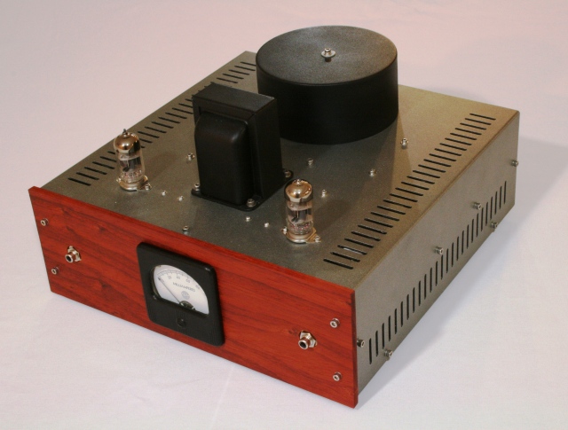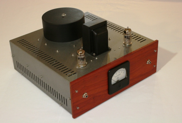
The Trick-Shot 6S45P-E / WE 437A Amplifier is ready for a permanent home. This has been a fun project for me, and exceeded all expectations for performance. The design and build process has been pretty well documented – keep scrolling down for more details. The Slicksheet Details are as follows:
- 1 watt per channel Single Ended 6S45P-E or 6S15P Triode Stereo Amplifier. WE437A supported via adapter.
- 60Kohm input impedance
- UTC Grid Chokes
- LED bias
- Tamradio (Tamura) Output Transformers.
- 4/8/16+ ohm speaker compatibility.
- THD (1KHz @ 1 Watt RMS) = 0.715%
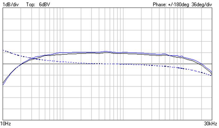
- Frequency Response (@ 1 Watt RMS): 20Hz to 20Khz +0.0/-1.0dB
- Western Electric Cloth Wrapped Wiring.
- CLCRC Power supply filtration.
- High Frequency mitigation in both signal chain and power supply.
- AC heater filaments
- No measurable or audible power supply hum.
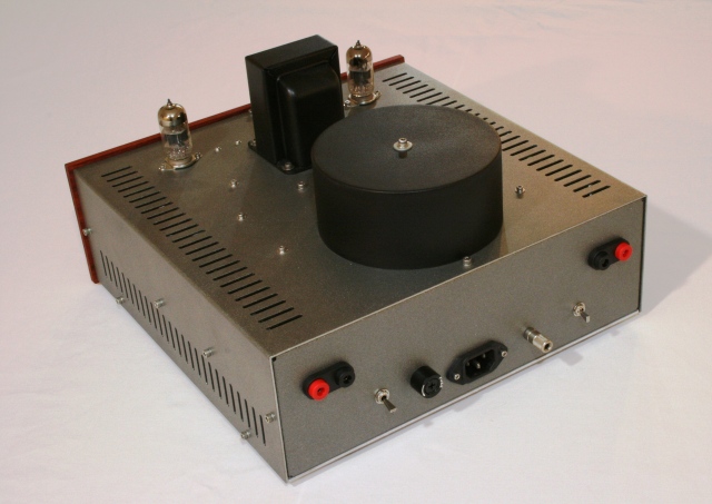
- 120 or 220 V line input
- Fused primaries
- Separate Chassis and signal grounds w/ ground lift switch
- Stainless Steel Fastening Hardware
- Heavy gage Aluminum Chassis
- Heat Cured Epoxy paint
- Clean point to point wiring
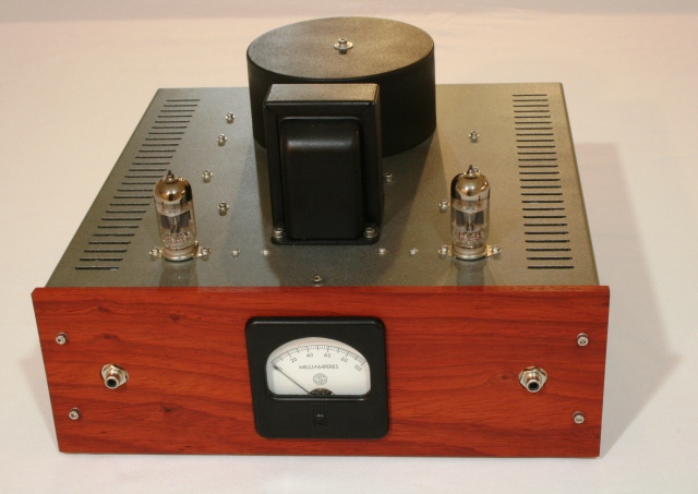
- Padouk Face panel.
- Common cathode bias meter.

On the subjective side, I find that the amp will easily drive to room filling sound with 90dB+ efficient speakers. Sound is the epitome of good single ended triode mojo. Soundstage and imaging are excellent, without smear. The sound floor is invisible – silent passages just roll off into inky darkness. The sound is engineered into the design – just the right amount of even order harmonics and mitigation of odd orders. Octave separation between the second and third harmonic is steeper on this amp than on anything else that I have built to date, and you can hear it in the results. Plenty of warmth, but with clarity, not the soupy sweetness that comes from overdoing a good thing. Perfect balance between accuracy and art. I can without shame admit that this is the most glorious 1 watt of triode output that I have been able to create in my 10+ years of building amplifiers.
This has been my main reference amp since January, but with autumn rolling around, it is coming time to say goodbye to this faithful friend to fund the next project.
Project details / History in Chronological Order:
9/7/2015:
This is the first in a series to document the build of the Trick Shot 6S45P-E amplifier. This will be my fourth spud amp using this fantastic cold war relic. Lots of schematics are out there for different variations on the theme, but the real trick to building a useful and rewarding amplifier around this triode is preventing unwanted noise pickup that can easily snowball into ultrasonic oscillation. This is an area that requires some design and fabrication discipline – the details of which will be fully documented as we progress.
Other than some signal integrity tricks, the amplifier itself is pretty straightforward:
- Russian 6S45P-E triode (or WE437, if you have the $$$)
- Idle conditions set at 214V Plate-Cathode, 30mA Cathode current for ~6.5 watts dissipation.
- LED bias.
- Grid Choke – vintage UTC .
- Tamradio Output Transformer 5kohm primary impedance / 8 + 600 ohm secondaries.
- No Feedback – none, nada, nyet!
9/10/2015:
Here is the generated anode load line for the Trick Shot Amplifier:

I have found that for most all triodes, the best sound to be had is by: 1) Idling them right at the dissipation limit, somewhere near the ‘knee’ in the dissipation curve. 2) Matching an anode load impedance that is as close to perpendicular to the linear region of the grid curves as possible, while still delivering the power output needed.
For the Trick Shot I had to compromise a bit in this respect – better linearity could be had with double (or more) transformer impedance, but power output would be below acceptable levels, even for highly efficient speakers.
Total plate dissipation is kept below 7 watts. The 6S45P-E can tolerate quite a bit more, but the WE437A cannot.
9/17/2015:
Given the load line generated previously, I know that I need to design a power supply that will deliver ~215V DC @ 64mA.
Power supply design is planned to be a simple CLCRC circuit with solid state rectification as diagrammed below. With this circuit, final output voltage can easily be tuned by adjusting values of the very first filter capacitor and the regulating resistor.
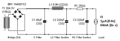
I have had good luck using the Duncan Amps PSU Designer II software, and am using it for this design. I highly recommend it to others based on performance, flexibility, and price (it’s free…) Available for download here: http://www.duncanamps.com/psud2/
In the circuit model above, I have entered actual measured parameters for the selected power transformer (ANTEK AS-05T200). Full specs are here.
The choke (vintage RCA) parameters are also as measured. All other parameters are from datasheets. Circuit load is modeled as a stepped current load. 1microamp for the first six seconds, stepping to the full circuit load of ~64 mA after that. This allows me to see just where the no-load circuit voltage peaks before the tubes begin to draw current, and to procure filter capacitors with appropriate DC voltage ratings.
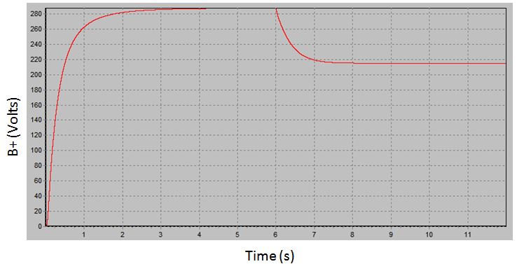
The plot below shows the modeled circuit behavior. You can see B+ float up to just a sneeze below 300 volts before the load kicks in and pulls it down to where I want it. To hold with a conservative 50% margin on voltage ratings, all the filter caps should be rated to at least 450VDC. In this case, pretty standard values for the first capacitor and filter resistor yield spot on desired voltage under the operating conditions called for on the load line generated previously.
Two last notes before moving on: 1) The first capacitor off the rectifier bridge should always be a quality film capacitor instead of electrolytic. This ‘hash-masher’ sees a lot more ripple and noise than the rest of the circuit, and the lower-ESR of film capacitors vs. electrolytics keeps the heat generation down and life to a maximum. 2) I have found it helpful to bypass each stage of filter capacitance with extremely low ESR polyester capacitors of 1/10,000 the value of the main filter capacitance (eg. 200uF Filter Cap, 0.02 uF polyester bypass). This helps to kill any High Frequency noise that has made its way into the circuit through the mains or inductive coupling across transformers.
9/19/2015:
I am still working procurement of power supply components, but here is one channel up and running on the protobench.
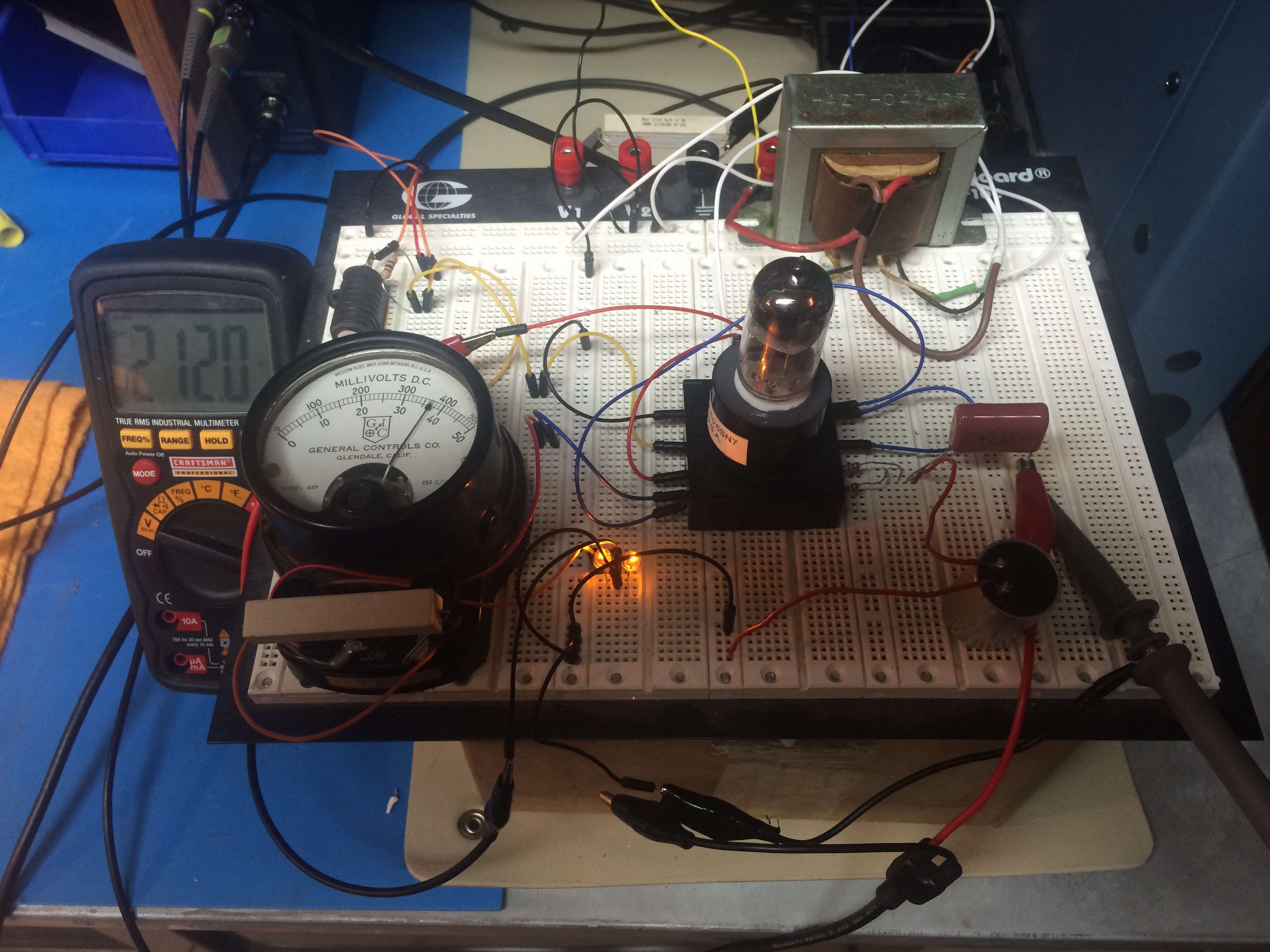
DC filaments fed with a lab power supply. B+ off a variaced Organ PS. Paralleled and current matched yellow LEDs for cathode bias. 1K gridstoppers. UTC grid choke (bottom right). 0.22uF AC coupling capacitor on the input. Idling at 212 Volts across the plate to cathode, drawing ~38mA.
Limited listening to this point, but bass response and top end sizzle are both excellent. Lots of punch and authority, clear instrument imaging with no smearing or soft focusing. Even with the less than clean signal routing, there have been no indications of ultrasonic or parasitic oscillation.
I always try to perform critical listening tests first before measuring the actual parameters for frequency response and harmonic content -allows me to tune by ear rather than against measured parameters that can lead one to pre-judge what should sound better on paper vs. the actual sonic experience.
The operating parameters above represent what I feel delivers the best sound. Listening at higher voltages / less current yields a sound with less harmonic content, but a dry sound. Going the opposite direction, the warmth really picks up, but you start losing instrument distinction and imaging. Over the weekend I will collect harmonics and output results for the three cases. Results to post when available.
10/9/2015:
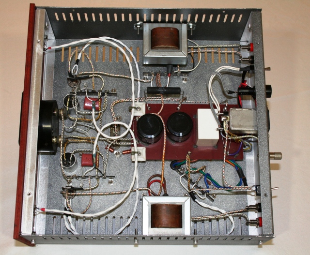
Here is the circuit itself. Just about as simple as you can get. I am using a grid choke in place of the typical grid bias resistor, but you can substitute in a 60-100k resistor if you are feeling cheap. The only critical component is the cathode bias LED. I bought a lot of 100 and screened them using the transistor test functionality on my old EICO 667 tube tester. I came up with about 16 out of that lot that exhibited excellent linearity and idled spot on at 35 mA with 2.7 volts across the diode. All 16 are now being burned-in to ensure that no drift occurs. The best two go in the amp, with the next best pair being retained as spares.

11/6/2015:
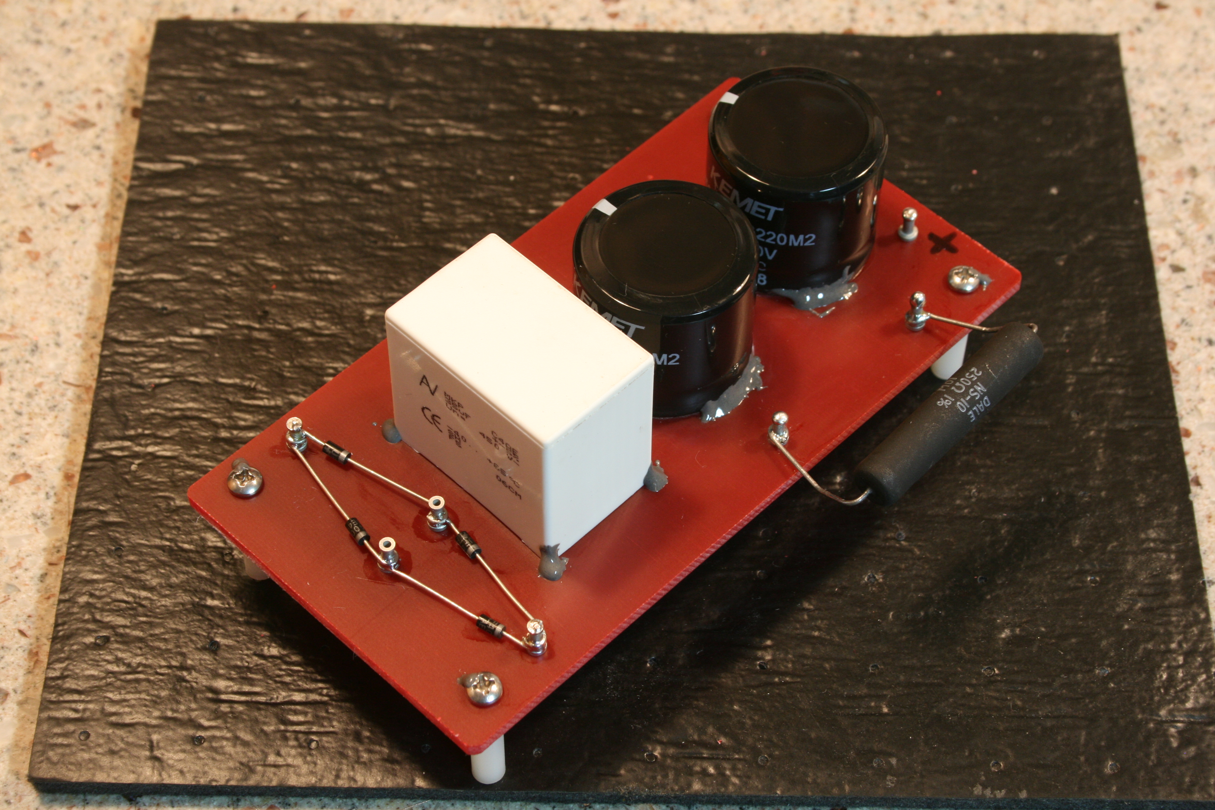
The B+ Power Supply Filter Block for the amplifier is now complete. Implementation is straight-forward CLCRC. Going AC to DC as follows: Bridge rectification with discrete 1N4007 diodes, followed by a 35uF Wima MKP series film hash-masher, a separate chassis mounted choke, fatty KEMET 220uF electrolytic, non-inductive 5W / 250 ohm wirewound resistor, and finally another 220uF capacitor. All the large value capacitors are bypassed with small capacity Panasonic ultra-low ESR poly caps to kill HF noise. The board itself is heavy red G10. All wiring is vintage solid core Western Electric that I had leftover from some old military radio salvage. Hi-pot / load test on the output to 10mA /500V and 125mA / 450VDC revealed no issues. Caps and hardware are all stake-bonded in place. Rectification diodes are staggered to place the body of each in close proximity to a terminal post for improved heatsinking.
11/6/2015:
Drilling and fitting has begun on the chassis. Here is the dry-fit of the power transformer. The cover is still in work. Chassis entry and exit for the AC line and HV taps are diametrically opposed, with the filaments offset at 45 degrees. The DC filter block from the previous post will mate on the chassis underside, directly under the transformer.
1/12/2016:
I took some time off to upgrade my shop lighting and heating, and have been slowly finishing the amp over the winter at a somewhat leisurely pace, usually predicated on the availability of new and interesting podcasts to listen to.
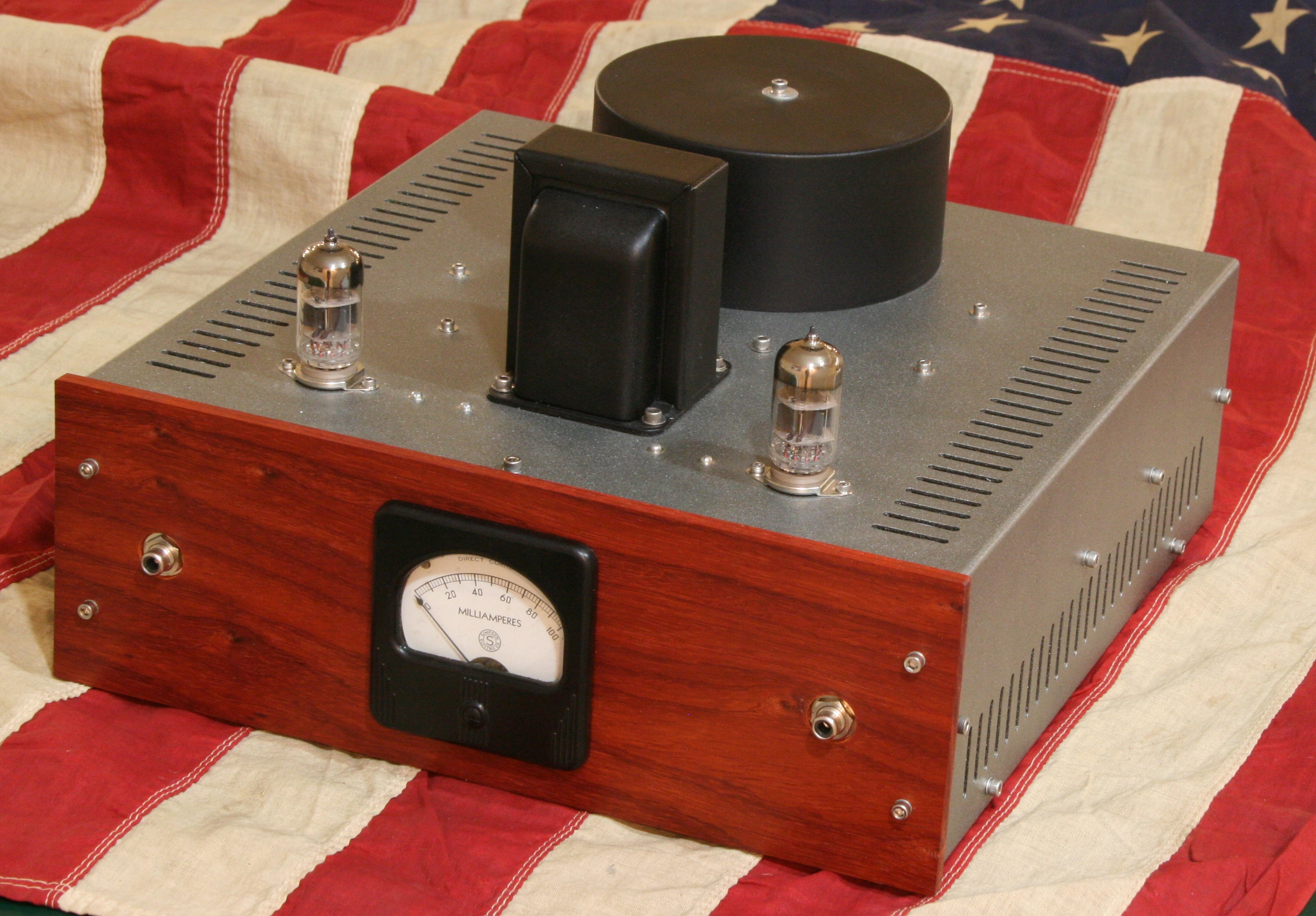
The finished product is even better than I had anticipated. The overall look and feel came in right as I wanted, and the sonics in stereo are even more magical than the mono prototyping setup. I am still in the process of completing the burn-in process, and will post the testable/measurable parameters like harmonic content and frequency response once I hit around 40 hours of total run time.
Subjectively speaking, the sound is very good, and I can drive it to very solid listening levels with high-efficiency speakers without clipping or noticeable distortion.
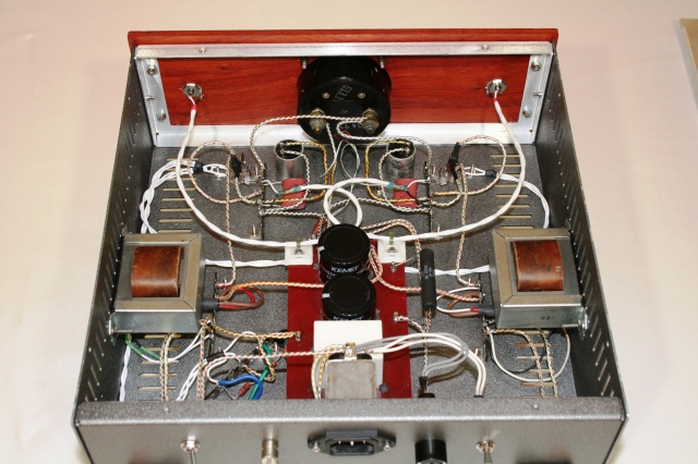
The extra work that went into signal integrity and noise reduction paid off in spades – the noise floor is sonically non-existent, and interference and hum have been banished as well. For details, I implemented separate isolated grounds – a ‘clean’ common power and signal ground, isolated from the ‘dirty’ chassis ground that also services the signal shields. Given that everyone has different setups and preferences, I have also added a switch that can be used to tie both grounds together, as well as a ground lug (chassis dirty) for you to use if using isolated input grounds on your preamp or phono stage.
Tube cathodes have a ferrite block, and each of the pair of grid pins has a separate grid stopper resistor.
Wiring is clean and logically routed to avoid noise and hum pickup and interaction. Heaters are AC, with a 100 ohm reference back to the ‘clean’ ground.
I also credit a good portion of the sonic mojo to the grid chokes used in place of grid leak resistors – compared to other iterations of this circuit that I have built that did not implement grid chokes, this one just has a bit more air and soundstage.
The esthetics of the system came out pleasing to the eye as well. I wasn’t sure about the red Padouk faceplate contrasting with the darker chassis tones, but once it was mounted with the current meter installed, I knew it was going to work. I like minimally processed wood finishes that build character with time. This one came straight off the planer and was treated to a single light application of IPA followed by a stretched application of flat tung oil. This ensures it will continue to patina as it ages, taking on a darker and richer hue.